J'avais trouvé cet article très interressant et très instructif, cependant , l'ayant recopié à part il y a longtemps , je ne sais plus de quel site il provient.
Je vous le livre brut, en anglais afin de vous en faire profiter .
merci à son auteur .
Enjoy ;)
Interfacing with SIOC
Although SIOC has been consigned to the realm of confusion for many eager cockpit builders, it really isn't that difficult to use. In fact, the case is most often that one can use an existing script written by someone else (or, for that matter, written by Opencockpits; they have loads on their website). Whenever a script isn't available, it is usually possible to modify an existing script; this can be done easily.
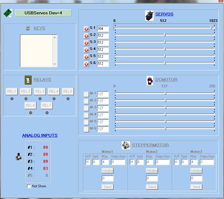
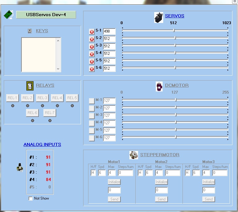
The first stage when interfacing any servo driven gauge through SIOC is to once again open up the SIOC servo testing application. Once within the application, the user should move the arrow slider to find the far left, centre and far right needle position(s) of the respective gauge. Here, we shall use the EGT gauge as an example, and interface it to FSX using the engine EGT data (this particular example will work with any FSX aircraft, and should the aircraft have more than one engine, it will default to lefthand engine number 1). Properly speaking however, the EGT gauge found within the Opencockpits set should be used for 737 APU EGT. However, having a 767 cockpit, my use for this particular gauge is somewhat none existent!
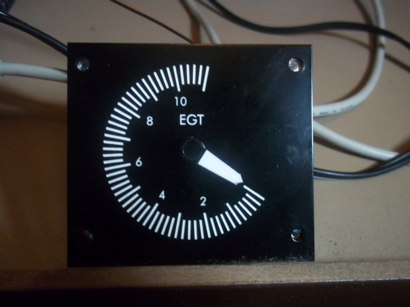
At this stage, we shall only discuss the operation of those gauges with linear scales such as the EGT gauge. The left, centre and right positions of the gauges found using the testing application were as follows:
 |
 |
 |
 Left/Minimum |
 Centre/Middle |
 Right/Maximum |
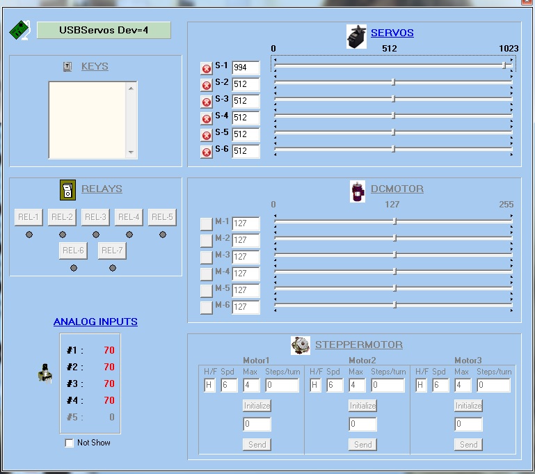
There are several important things to note here. Firstly, the far “lefthand” position, due to the way the EGT gauge is orientated, actually appears to the right of the gauge. Although SIOC uses the words “left”, “right” and “centre”, it is perhaps more accurate to use the words “minimum”, “maximum” and “middle” since not all gauges default to a generic “left/right” structure. So, with reference to the photographs:
LEFT/MINIMUM Position = 994
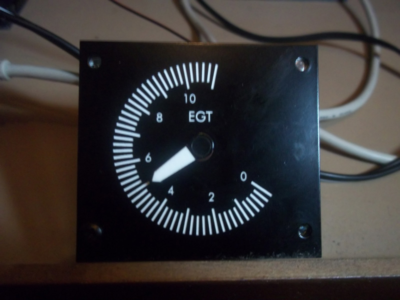
CENTRE/MIDDLE Position = 498
RIGHT/MAXIMUM Position = 1
NOTE: The actual “maximum” position is 0, not 1; the slider can be moved one more step if needed. However, out of force of habit I never use the “extreme” values when programming, I always use at least one less; call this a ritualistic force of habit if you will, it just feels easier on the servo motor to not push it to the hard-stop of its mechanism. Furthermore, with the way Opencockpits have constructed the gauge, 1 value is equal to 1 degree, and thus for the sake of one degree, I am happy not to use the “extreme” value. Also note that the “middle” position is nothing special, it is simply the halfway point between the maximum and minimum values. These figures are used in the SIOC script (see below).
Secondly, it can be observed that as the servo value on the servo testing interface within SIOC decreases, the EGT gauge value increases. This is simply because of the way the servo has been installed; SIOC is turning the gauge “backwards” - this is significant when we come to program the gauge since we must multiply any FSX values by -1 to turn the gauge “forwards”.
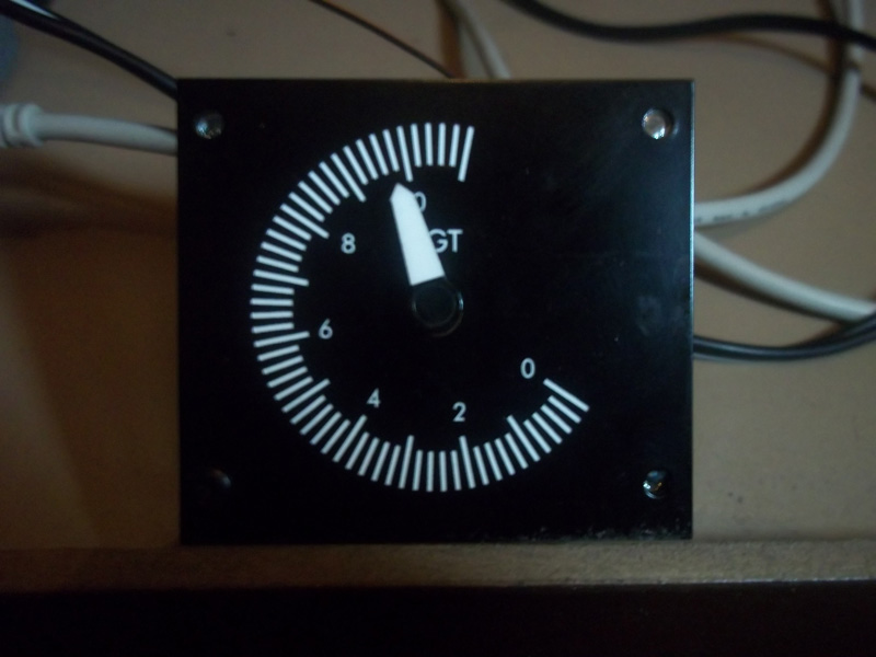
Finally, as proven in the photograph, the gauge does not move all the way to the end of the scale, peaking at around 990 degrees. Whilst this does not present a problem for the most part, since most normal EGT applications (especially a 737 APU as is the case here) will not reach or exceed such a temperature, it is a little annoying knowing that there is part of the gauge that the needle will never reach.
Furthermore, when I initially inspected the EGT gauge, the needle did not zero properly; the needle reached a minimum point at around 100 degrees. I had to manually rotate the needle whilst locking the gearing mechanism (to prevent damage to the servo motor) in order to get proper operation from the gauge. Clearly, this is a significant problem since one should not have to force a needle into position.
Having used the testing software to find the EGT gauge needle values, I wrote a quick SIOC script to allow the EGT needle to run off the Engine 1 EGT data from FSX. Once again, I must stress that this gauge is meant to be used with 737 APU EGT data; the only problem is that I do not have any 737 software installed on my PC.
This was the script, with annotations explained below.
////////////////////////////////////////////////////////////////////////////////////////////////////////////////////////
Var 0001, name EGT, Link FSUIPC_IN, Offset $3B70, Length 8 // EGT from Sim
{
L0 = &EGT - 459.67 // FSUIPC Conversion Rankine -> Farenheit
L0 = L0 - 32 // FSUIPC Conversion Farenheit -> Celsius
L0 = L0 * 5
L0 = L0 / 9
L0 = ABS L0 // L0 not signed
L0 = L0 * -1
L0 = L0 + 994
&EGT_Gauge = L0
}
Var 0002, name EGT_Gauge, Link USB_SERVOS, Output 1, PosL 1, PosC 498, PosR 994 // EGT Gauge
////////////////////////////////////////////////////////////////////////////////////////////////////////////////////////
Explanation of each line of code:
I have tried my hardest to keep explanations short and simple here. Should you require any further assistance, or have any further questions, please do not hesitate to contact me through the Mutley's Hangar forum.
Var 0001, name EGT, Link FSUIPC_IN, Offset $3B70, Length 8 – This line of SIOC code tells SIOC which FSUIPC offset we want to use, and then tells SIOC the “length” of the offset in bytes. Whenever we want to introduce an FSUIPC offset into a SIOC script, it must be defined as a variable. A variable is, as the name suggests, anything that can vary (or, more appropriately, anything that can have a value of some sort). A variable could be a switch, annunciator, lever; whatever – in this case, our variable is the exhaust gas temperature.
To define a variable, start a line of code with “Var XXXX”, whereby XXXX is any number between 0001 and 9999. You can also name a variable; note the “name EGT” part of the script just after we have defined the variable. “EGT” is what I have chosen to name the variable here, it could of course be anything you like (or, the “name” section of code can be omitted completely).
“Link FSUIPC_IN” tells SIOC that we want to extract information FROM the variable, and not the other way around (which would be “FSUIPC_OUT”). This is somewhat obvious since we are taking information FROM FSX to drive our EGT gauge. “FSUIPC_OUT” would be used in the case of a switch or something similar, where we are sending information TO FSX.
“Offset $3B70” is simply the offset number for the EGT engine 1 value; for any other offset the code will be different. FSUIPC offsets are always entered into SIOC in the form “Offset $XXXX”, whereby XXXX is the respective four digit code for the offset (found in the FSUIPC “Offsets Status” PDF file in the FSUIPC SDK). Many people often forget to put the dollar sign in front of the offset number; if this is not done, SIOC will reject the code. Finally, “Length 8” tells SIOC the offset is 8 bytes in length; this information is also found in the FSUIPC SDK.
L0 = &EGT – 459.67... - This entire section of calculations between the two curly brackets, although visually complex, simply converts the FSUIPC EGT (which is in degrees Rankine) into degrees Celsius. This code is, of course, different if one wishes to use Farenheit, however since the Opencockpits gauge is presented in degrees Celsius, coding for Farenheit would be a somewhat foolish move.
The “L0” entries seen at the start of some of the lines are examples of Internal Integer Variables. Due to the nature of SIOC, one cannot tell SIOC to do more than one calculation per line of script, and so there must be a way of “holding” values between one line and the next, otherwise one could only ever do simple single step calculations. The answer is to write “L0 =”, then the desired calculation, and then repeat “L0 =” on the next line, with “L0” having held the value from the previous line. “&EGT_Gauge = L0” sends the final value of “L0” (which by this point is the EGT in degrees Celsius) to the EGT gauge variable, which is explained below. The ampersand symbol (“&”) is necessary when referencing a named variable, or again SIOC will reject the code.
Var 0002, name EGT_Gauge, Link USB_SERVOS, Output 1, PosL 1, PosC 498, PosR 994 // EGT Gauge – This line defines the variable that is our EGT gauge; it tells SIOC we have a servo motor and then tells SIOC information about this servo motor.
The sections “Var 0002” and “name EGT_Gauge” serve a similar function to those explained on the “Var 0001” line. “Link USB_Gauge” tells SIOC that this variable is linked to an EGT gauge (in a similar way to how “FSUIPC_IN” told SIOC we were linking the variable to FSUIPC information).
“Output 1” tells SIOC that our servo motor is connected to position 1 on the USBServos card. “PosL 1, PosC 498, PosR 994” simply tells SIOC the left, right and centre positions of the gauge as previously explained.
And that's it! The scripts required for the other gauges are not discussed here since they largely follow a very similar concept, with the only changes being different offset values and different servo position values.
Aucun commentaire:
Enregistrer un commentaire
Remarque : Seul un membre de ce blog est autorisé à enregistrer un commentaire.